


Ultrasonic webbing cutting and welding principle application
Principle of Ultrasonic Cutting and Welding
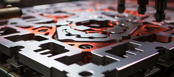
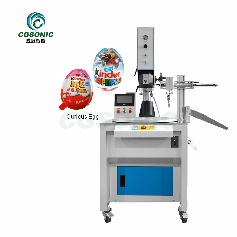
Ultrasonic cutting and welding is a sub-field of ultrasonic applications in industry, and it has been increasingly widely used due to its environmentally friendly, efficient, and aesthetically pleasing characteristics.
Ultrasonic cutting and welding principle
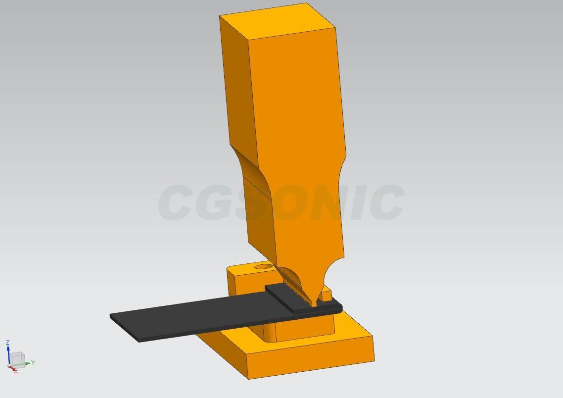
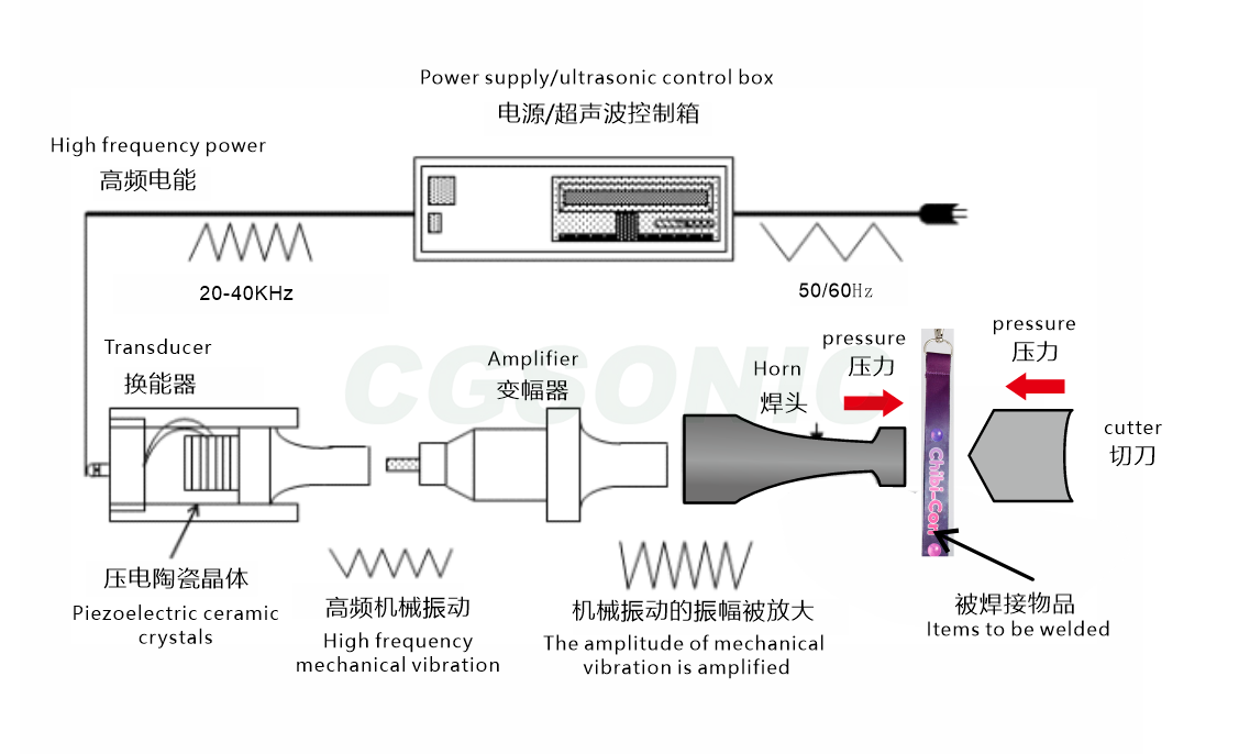
Ultrasonic webbing cutting and welding utilizes high-frequency mechanical vibration of 20-40kHz , transferring energy to the webbing contact surface through the welding head. 1. Energy Conversion: The ultrasonic generator converts electrical energy into high-frequency mechanical vibration, which is amplified by the amplitude transformer and then transmitted to the welding head. 2. Frictional Heat Generation: The welding head presses against the webbing, causing high-frequency friction between the fibers inside the webbing, instantly generating localized high temperatures of 500-1000℃ . 3. Synchronous Welding and Cutting: The high temperature melts the webbing fibers (such as nylon and polyester), while the welding head pressure compacts the melted portion, forming a strong weld layer. If used with a specific cutting edge welding head, the high temperature can simultaneously cut the webbing, achieving integrated "cutting + welding". 4. Cooling and Shaping: After vibration stops, the pressure is maintained for 0.1-0.5 seconds, allowing the welded area to cool and solidify rapidly, completing the cutting and welding process. (Pneumatic systems provide cushioning, also ensuring cooling and shaping during the cutting and welding process.)
Composition of ultrasonic cutting and welding system
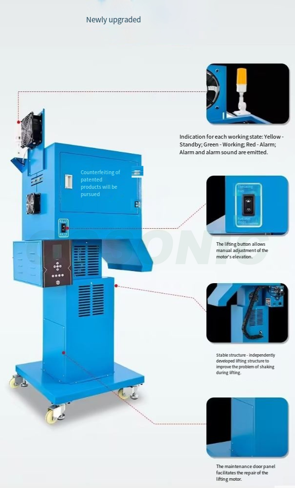
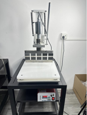
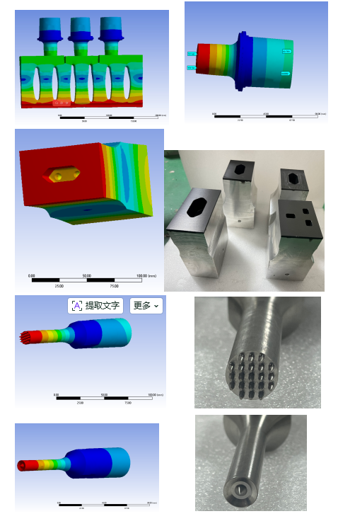
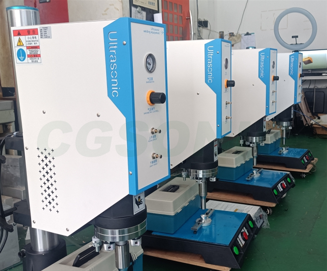
The commonly used ultrasonic plastic welding system consists of three main components: an ultrasonic generator (electrical box), an ultrasonic transducer (vibrator), and an ultrasonic mold (mold head, welding head, horn) .
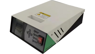
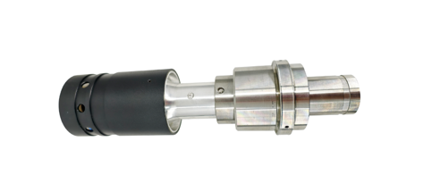
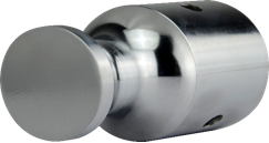
Ultrasonic generator (electrical box) Ultrasonic transducers (vibrators), ultrasonic molds (mold heads, welding heads, horns)
1. Ultrasonic generator (electrical box): Converts mains power into a stable high-frequency, high-voltage output.
2. Ultrasonic transducer (oscillator): An acoustic device that converts energy, transforming electrical energy into mechanical energy.
3. Amplifier: The amplitude of the transducer's mechanical vibration is changed through a pre-designed gain ratio.
4. Molds (welding heads, horns): Customized to specific dimensions according to the needs of welding and cutting applications, and designed with acoustic characteristics to meet the resonance requirements of the ultrasonic system. Below, I will use several formulas to explain the parameter tuning phenomenon in applications.
Energy = Amplitude * Pressure * Time * Constant K = Power * Time
The formulas above show that in welding and cutting, the amplitude of the ultrasonic wave (which can be set on the generator), the pressure (air pressure or electric cylinder torque, as well as structural rigidity and hardness), and the wave emission time are positively correlated with the welding and cutting effect. In other words, if the product is not cut well, these parameters can be adjusted positively. Does this mean that the higher these parameters are, the better? Of course not!
P = K∗A∗f∗δ, where P represents welding power, in W ;
K is a constant whose magnitude is related to the sound conduction and energy dissipation of the material. This means that we usually say that different materials need different parameter fine-tuning to meet the requirements.
A represents the area of the weld cut, measured in square meters (㎡). This is the contact surface of the weld cut, so the length and angle of the cutting edge usually determine this area.
f is the ultrasonic frequency, meaning that theoretically, higher frequencies are easier to weld. However, acoustically, the higher the frequency, the more difficult it is to achieve a large amplitude; the unit is Hz .
δ represents the amplitude, measured in meters ( m) . Theoretically, a larger amplitude results in better welding and cutting. However, the fatigue life of metallic materials is related to frequency, material properties, stress, time, pressure, and hardness, and is therefore affected by other parameters.
Six factors affecting ultrasonic cutting and welding results:
Pressure + Time + Mechanical Structure + Product Materials + Debugging
1. Ultrasonic welding pressure
Applying appropriate pressure to the welding surface causes the welding material to transition from elastic to plastic, promotes molecular interdiffusion, and displaces residual air from the weld, thereby increasing the sealing performance of the weld surface. The pressure generally does not exceed 0.5 MPa.
2. Ultrasonic welding/cutting time (wave emission time)
Appropriate melting time and sufficient cooling time are essential. With a fixed heat output, insufficient time will result in incomplete welding, while excessive time will cause deformation of the weldment, slag overflow, and sometimes hot spots (discoloration) in non-welded areas. It is crucial to ensure that the weld surface absorbs sufficient heat to reach a fully molten state to guarantee adequate molecular diffusion and fusion. Simultaneously, sufficient cooling time is necessary for the weld to achieve adequate strength.
3. Ultrasonic amplitude
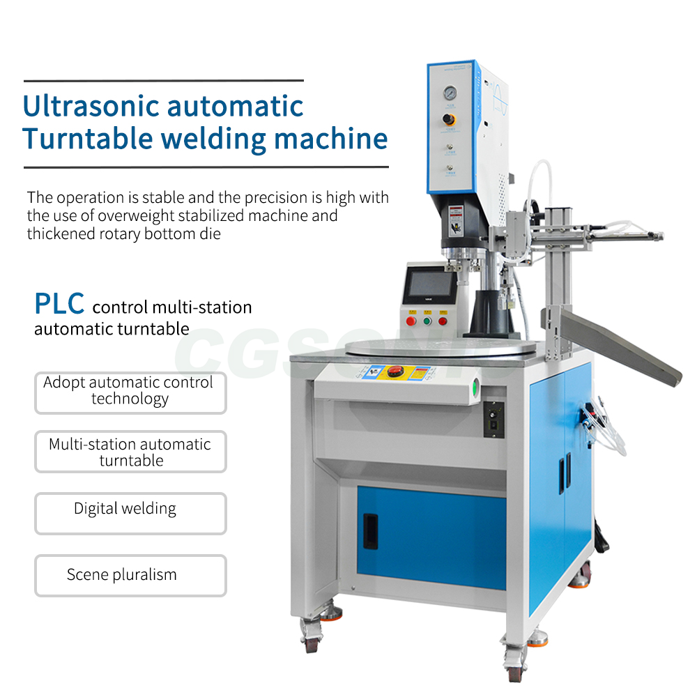
4. Mechanical structure
The precision and stability of the frame manufacturing directly affect the welding effect, especially for some precision products, where the mechanical structure must match the product's precision.
5. Product Materials
Factors such as the material of the welded parts, their structure, thickness, and pressure resistance also directly affect the welding effect.
6. Equipment debugging
In conclusion, for a product to achieve the best ultrasonic cutting and welding results, equipment debugging is also an important guarantee. Flexible matching and adjustment of various parameters and on-site debugging by engineers play an important role.