





11 Common Ultrasonic Plastic Welding Defects and How to Solve Them (with Quick Troubleshooting Roadmap)
Last updated: August 20, 2026 | Author: [Li Yong] (Ultrasonic Welding Process Engineer) | Reading time: approx. 12 minutes
|
About This Article Compiled by Li Yong, an ultrasonic welding process engineer at Shenzhen Chengguan Intelligent Ultrasonic Equipment Co., Ltd. With 22 years of experience in production-line commissioning and yield improvement, he has delivered more than 10,000 welding projects covering over 100,000 welded products. The content of this article is based on real production-line cases and parameter validation. |
Table of Contents
- Cold Welding (False Welding)
- Over-welding (Burn Marks, Charring)
- Excessive Flash and Overflow
- Product Deformation and Warping
- Cracks and Splitting
- Weld Misalignment and Mismatch
- Indentations and Dents (Surface Pressure Marks)
- Bubbles and Porosity
- Poor Sealing (Water and Air Leakage)
- Inconsistent Welding Quality
- Rattling Noise After Welding
- Quick Troubleshooting Roadmap
- Frequently Asked Questions (FAQ)
Ultrasonic plastic welding has become the mainstream assembly process in automotive interiors, electronics housings, medical devices, home appliance parts, and many other fields, thanks to its speed, high consistency, and freedom from consumables. In actual production, however — influenced by material condition, parameter settings, tooling wear, fixture precision, and other factors — welding defects are a problem almost every production line runs into.
This article systematically walks through the 11 most common ultrasonic welding defects found in production. Each defect is broken down into three levels: "Symptom → Cause → Solution." A quick troubleshooting roadmap is included at the end to help you rapidly locate the root cause when something goes wrong on the line and cut down trial-and-error time.
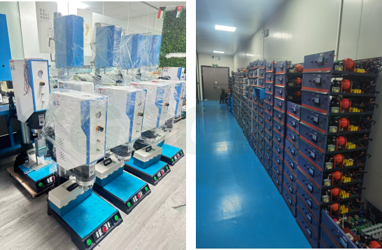
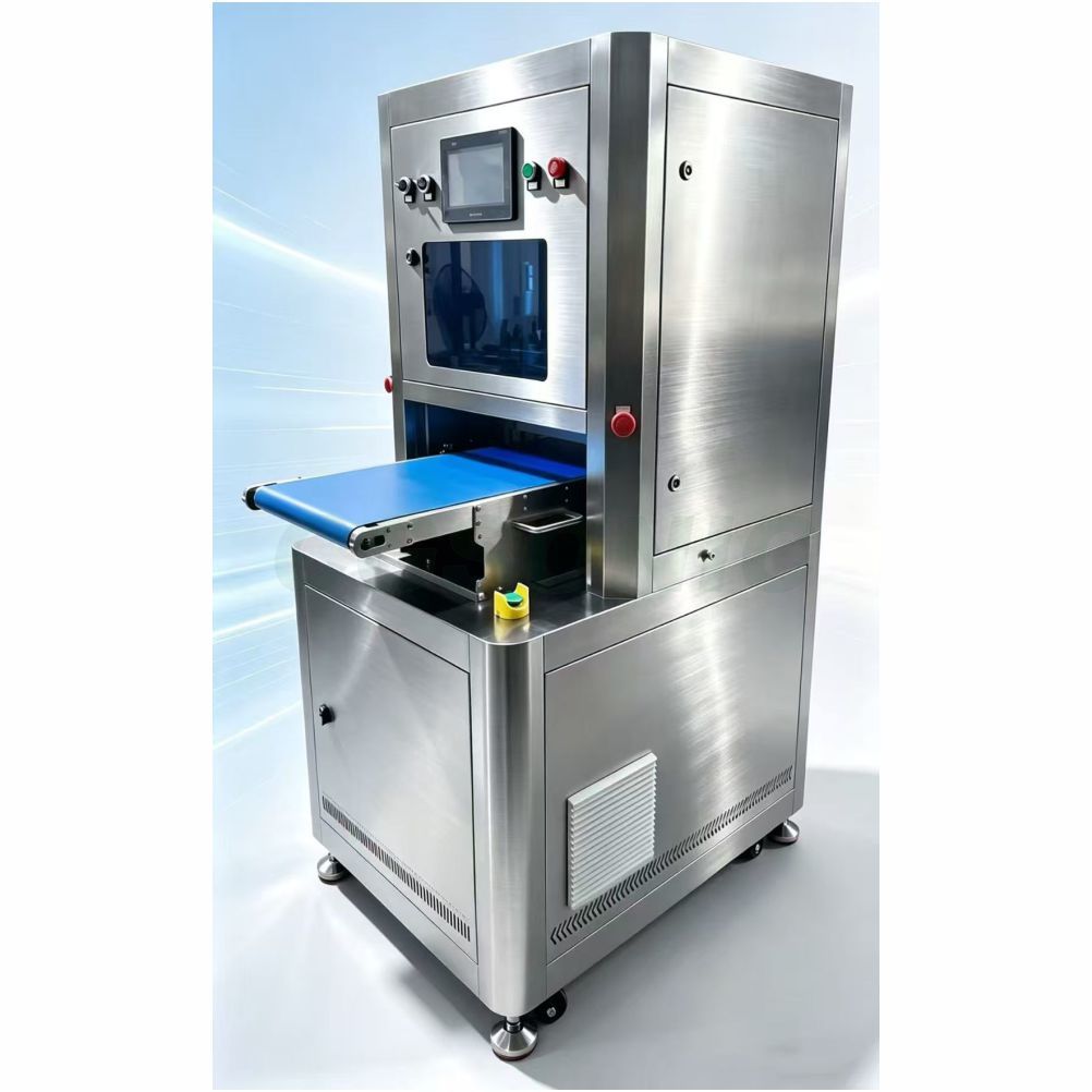
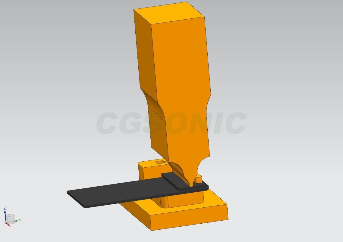
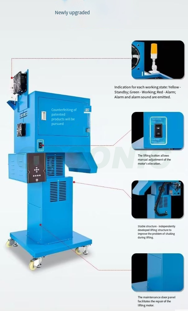
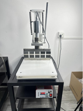
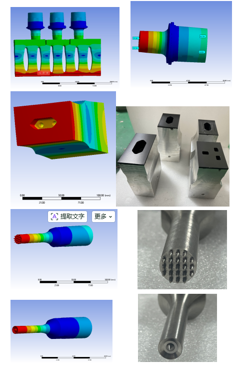
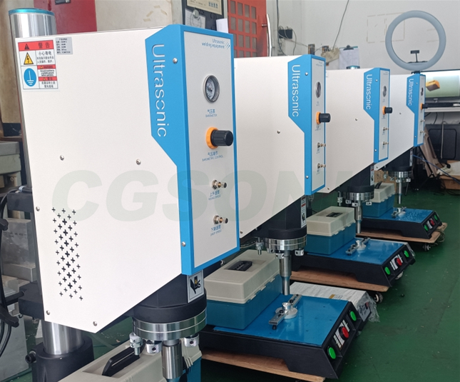
Ultrasonic plastic welding equipment Production line photos
1. Cold Welding (False Welding)
Symptom
The weld seam looks fully formed, but it breaks apart with a light twist by hand and its strength falls far below the design requirement; in peel tests the upper and lower housings simply separate. Cross-section inspection shows that no real fusion has taken place inside — the energy directors have merely been "flattened" instead of forming a molten nugget.
Causes
- Insufficient welding pressure, welding time too short, or amplitude too low — energy input below the fusion threshold
- Worn horn or fixture, reducing energy-transfer efficiency
- Product misaligned in the fixture, so the energy directors do not line up with the horn's pressure point
- Excessive moisture in the plastic resin; vaporizing water carries away heat and blocks fusion
- Energy directors too small in the product design — not enough meltable material
Solutions
- Increase welding pressure, extend welding time, or raise amplitude output as appropriate (adjust only one parameter at a time, and record the comparison)
- Inspect the working faces of the horn and fixture; rework or replace worn ones promptly
- Optimize the fixture to guarantee accurate, non-offset product positioning
- Dry the plastic resin beforehand to remove moisture (for ABS/PC, bake at 80–100°C for 2–4 hours)
- Modify the product structure to enlarge the energy directors (typical director height is 0.5–0.8 mm, depending on the material wall thickness)
2. Over-welding (Burn Marks, Charring)
Symptom
The weld seam turns white, yellow, or even charred black; flash is heavy and the part deforms; in severe cases it burns through locally. Most often seen on small parts, thin-walled parts, or products with oversized energy directors.
Causes
- Excessive welding time, amplitude, or pressure — energy input per unit area over the limit
- Ultrasonic dwell (hold) time too long; heat keeps accumulating with nowhere to dissipate
- Product wall thickness on the thin side — it cannot withstand standard parameters
Solutions
- Reduce welding time, decrease amplitude, and lower welding pressure
- Shorten the ultrasonic dwell/hold time
- Reduce overall energy input for thin-walled products; if necessary, work with the structural engineer to optimize wall thickness
- Adjust the horn contact position to keep energy from concentrating on local weak points
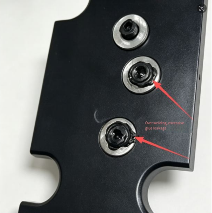
3. Excessive Flash and Overflow
Symptom
A ring of excess plastic burr is squeezed out along both sides of the weld seam. It spoils the appearance and has to be trimmed off by hand afterward, adding cost.
Causes
- Welding pressure too high, or the collapse (downstroke) depth set too deep
- The material flows easily, so molten plastic is readily squeezed out
- The fit gap between the upper and lower housings is too large, giving the melt an "escape path"
- The horn's contact face is not flat, creating excessive local pressure
Solutions
- Lower the welding pressure and reduce the collapse-depth setting
- Optimize the injection molding of the product to tighten the housing fit gap
- Service and re-grind the horn to keep the contact face flat
- For free-flowing plastics (such as PP), lower the amplitude to reduce the amount of molten plastic squeezed out
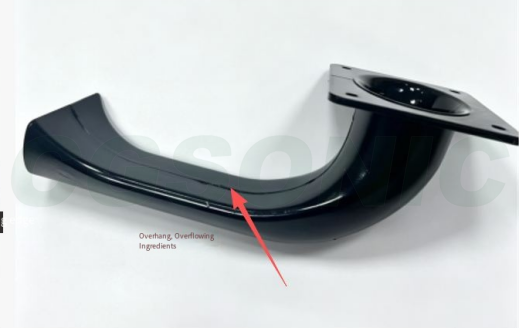
4. Product Deformation and Warping
Symptom
After welding, the housing bends or bulges and the snap features deform, throwing downstream assembly out of alignment — sometimes to the point where the snaps no longer fit at all.
Causes
- High clamping pressure with heat stress concentrated locally
- Insufficient fixture support; unsupported areas of the part collapse under pressure
- Uneven wall thickness in the part itself, causing inconsistent cooling shrinkage
- Pressure released before the cooling (hold) time is sufficient, while the plastic has not yet set
Solutions
- Reduce the welding clamping pressure
- Optimize the fixture/nest to give the product full back support and eliminate unsupported areas
- Improve wall-thickness uniformity in the product design as far as possible
- Extend the hold/cooling time; release pressure and open the tool only after the plastic has cooled and set
5. Cracks and Splitting
Symptom
Cracks appear near the weld seam, in thin-wall sections, or at corners. They are more common in brittle materials (ABS, PC) — PC especially.
Causes
- Excessive ultrasonic energy; the high-frequency vibration impact literally "shakes" the material apart
- The horn presses directly on a thin-wall area, concentrating stress
- High internal stress in the molded part; welding heat triggers stress release
- Stress concentration at sharp corners of the part
Solutions
- Reduce amplitude and total welding energy to lessen the impact
- Change the horn contact position to avoid thin-wall areas
- Anneal the molded parts in advance to relieve internal stress
- Round off the sharp corners in the product structure to eliminate stress-concentration points
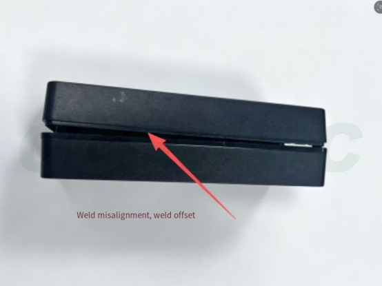
6. Weld Misalignment and Mismatch
Symptom
The joint between the upper and lower housings shows a large step and uneven heights — a cosmetic defect that can also compromise sealing in severe cases.
Causes
- Poor positioning-fixture accuracy
- Large fit gap in the product's injection mold
- The horn is not mounted vertically and has a lateral offset
- The part is subjected to lateral force during clamping
Solutions
- Calibrate and overhaul the positioning fixture to improve positioning accuracy
- Improve the injection mold to tighten the housing fit gap
- Correct the horn installation to ensure verticality and eliminate lateral offset
- Adjust the fixture so the part is never loaded sideways during welding
7. Indentations and Dents (Surface Pressure Marks)
Symptom
Marks or dents are pressed into the part's outer surface by the horn, ruining the appearance. For cosmetic parts (remote controls, speaker panels, etc.) this is usually a fatal defect.
Causes
- Excessive welding pressure
- Amplitude transmitted through to the cosmetic surface
- Inappropriate horn hardness or surface texture
- No support behind the part, so it sinks under pressure
Solutions
- Lower the welding pressure
- Add a protective buffer film between the horn and the cosmetic surface; optimize the horn's surface texture
- Add full back support in the fixture to keep the part from sinking under pressure
- Reduce amplitude to limit vibration reaching the cosmetic surface
8. Bubbles and Porosity
Symptom
Bubbles appear inside the weld seam — directly visible to the naked eye in transparent parts — reducing strength and compromising sealing.
Causes
- High moisture in the plastic; it vaporizes during welding and gets trapped in the seam
- Gas inside the molten material cannot escape
- Welding too fast; the molten plastic seals over too early and traps air
Solutions
- Fully dry the plastic resin to drive off moisture
- Slow the welding speed appropriately to give gas time to escape
- Adjust the pressure parameters so the melt is fully compressed and internal gas is squeezed out of the seam
9. Poor Sealing (Water and Air Leakage)
Symptom
Tensile strength is acceptable, but the part fails air-leak or water-immersion tests. Common in waterproof housings, automotive sensors, liquid-cooled parts, and other sealing-critical products.
Causes
- Cold welds: fusion is discontinuous in places, leaving gaps in the seam
- Oil or dust on the mating surfaces contaminating the fusion interface
- Damaged or poorly designed energy directors — not enough melt to fill the sealing path
- Fluctuating welding parameters; fusion varies from part to part
Solutions
- Troubleshoot cold welding first (see Section 1) and fine-tune the welding parameters so the seam fuses continuously all the way around
- Clean the part's mating surfaces before welding to remove oil and dust
- Inspect the energy directors; where damaged, modify the product structure
- Stabilize the equipment's air pressure and voltage to reduce parameter fluctuation, and run leak-test spot checks on the line
10. Inconsistent Welding Quality
Symptom
Within the same batch, some parts weld soundly and others come out cold-welded; the defect rate swings widely, and parameters that were dialed in today are wrong again tomorrow.
Causes
- Fluctuating workshop power voltage
- Unstable compressed-air pressure
- Horn wear and resonant-frequency drift
- Batch-to-batch variation in the molded parts (moisture content, dimensions, internal stress)
- Inconsistent fixture positioning clearance
Solutions
- Fit the equipment with a voltage stabilizer and stabilize the air supply pressure
- Check horn resonance regularly; repair or replace worn horns promptly
- Control incoming molded parts and standardize the molding process to reduce batch variation
- Overhaul the fixtures so every part is held with the same positioning clearance
11. Rattling Noise After Welding
Symptom
A fine rattling sound comes from inside the finished part when it is shaken. Common in closed-cavity products (remote controls, sensor housings).
Causes
- Plastic debris from over-welding left inside the cavity
- Flash breaking off and falling into the product
Solutions
- Optimize the parameters to avoid over-welding and cut debris at the source
- Improve the weld-seam design so flash cannot break off into the cavity
- Add an air-blow cleaning step after welding to clear debris from the cavity
- Control flash and overflow; add a trimming step if necessary
Quick Troubleshooting Roadmap
When a welding abnormality comes up, don't start blindly twisting parameters. Troubleshoot in the order below — it covers 90% of problems:
① Material drying → ② Product fit clearance → ③ Horn/fixture condition → ④ The three main parameters: pressure, time, amplitude
First confirm the material condition (moisture, batch), then check the part's own fit tolerances, then inspect the horn and fixture for wear or offset — and only then start adjusting parameters. Do it in the reverse order and you will usually burn time heading in the wrong direction.
Frequently Asked Questions (FAQ)
Q: How do I fix cold welding (false welding) in ultrasonic welding?
A: First check whether the three main parameters — pressure, welding time, and amplitude — are set too low; then check whether the horn/fixture is worn or the part is misaligned. Excessively moist plastic also causes cold welding, so dry the material before welding. If the energy directors are too small, the product structure must be changed to enlarge them.
Q: Why do ultrasonic welds turn white or get burned?
A: That is classic over-welding. The causes are excessive welding time, amplitude, or pressure, or an overly long ultrasonic dwell that lets heat build up. The fix is to cut welding time, reduce amplitude, lower pressure, and shorten the hold time. Thin-walled products need particular care with energy input.
Q: What should I do if the part deforms or warps after ultrasonic welding?
A: Reduce the welding clamping pressure and optimize the fixture to give the part full back support; extend the hold/cooling time and release pressure only after the plastic has cooled and set. Uneven wall thickness in the part itself also worsens deformation and should be improved at the design stage.
Q: What is the difference between ABS and PC in ultrasonic welding?
A: ABS is an amorphous material with excellent ultrasonic weldability that fuses easily. PC is also amorphous but has a higher melting point and greater stiffness, so it needs higher amplitude and energy; it is also sensitive to internal stress — annealing before welding is recommended, otherwise cracks appear easily.
Q: How do I troubleshoot on-and-off, inconsistent ultrasonic welding?
A: Troubleshoot in this order: 1) power voltage fluctuation — install a voltage stabilizer; 2) whether the air supply pressure is stable; 3) horn wear and resonance drift — check regularly; 4) batch variation in molded parts — standardize the process; 5) whether the fixture positioning clearance is consistent.