






Complete Guide to Ultrasonic Welding Parameter Settings: 14 Key Parameters Explained (Engineer's Practical Version)
Complete Guide to Ultrasonic Welding Parameter Settings: 14 Key Parameters Explained (Engineer's Practical Version)
This article was compiled by Li Yong , an ultrasonic welding process engineer at Shenzhen Chengguan Intelligent Ultrasonic Equipment Co., Ltd. , who has 22 years of experience in production line debugging and yield improvement, and has delivered over 10,000 welding projects, covering the welding of over 100,000 products. The content of this article is based on real production line cases and parameter verification.
Table of contents
- Welding pressure
- Delay time 1 (startup wait)
- Welding time
- Holding pressure (curing) time
- amplitude
- Welding mode selection (time/energy/depth)
- descent speed
- Machine descent buffer
- Triggering pressure
- Delay time two (pre-pressure delay)
- Secondary vibration time (for cleaning the weld head)
- Machine travel fine adjustment
- Machine level calibration
- Total machine stroke
- 14-Parameter Quick Reference Table
- Parameter Tuning Decision Tree
- Frequently Asked Questions (FAQ)
I. Welding Pressure
effect
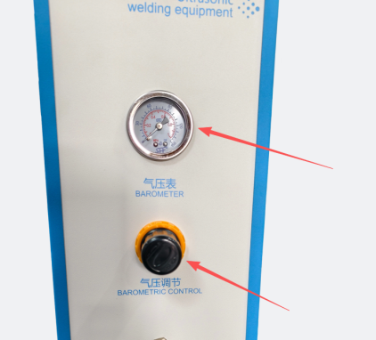
Welding pressure is fundamental to plastic bonding, determining the tightness of contact between the welding head and the product, and directly affecting whether vibration energy can be effectively transmitted to the weld.
Influence
- Insufficient pressure : The upper and lower products do not fit tightly, resulting in poor transmission of vibration energy and making it easy for incomplete welds and insufficient weld strength to occur.
- Excessive pressure : The plastic is forcibly squeezed, resulting in over-welding, flash, and product damage and deformation.
suggestion
- Medium pressure is preferred for ordinary plastic parts; pressure should be appropriately reduced for thin-walled and exterior parts; and pressure can be appropriately increased for rigid materials.
Debugging sequence: Gradually increase the pressure from low to high until you find the pressure that allows the product to fit tightly. Do not pursue "the tighter the better".
II. Delay Time 1 (Startup Waiting)
effect
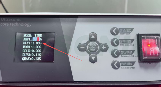
The waiting time from pressing the start button to the welding head starting to descend and output ultrasonic waves allows the operator time to confirm that the product is in place.
Influence
- Too short a delay : If the product is started before it is properly placed, it may cause the hand to be crushed or the product to shift, posing a safety hazard.
- Excessive delays reduce production cycle time and affect capacity efficiency.
suggestion
- For models with two-button operation, the timer will only start when both hands are pressed simultaneously to ensure operational safety.
- For standard products, set the time to 0.1-0.5 seconds; for products requiring manual placement and positioning, extend the time to 0.5-1.0 seconds.
III. Welding Time
effect
The duration of ultrasonic vibration output determines the amount of plastic that melts. Welding time is the parameter that beginners care about most, but it is also the parameter that is most often misadjusted.
Influence
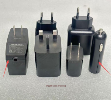
- Too short a time : Insufficient plastic melting, incomplete welding, and poor soldering.
- Too long : Excessive energy input leads to over-melting of the plastic, resulting in scorching, excessive flash, and product deformation.
suggestion
- The welding time for small and thin parts is generally 1-0.4s ; for medium and large parts , it is 0.4-1.2s , and can be finely adjusted according to the actual weld effect.
- Start with short durations and gradually increase; do not set long durations directly. If you notice burning or excessive burrs, immediately adjust back.
- For the first trial welding of a new model or new materials, it is recommended to start from 0.2s and test for 0.1s each time, recording the appearance and strength
IV. Holding pressure (curing) time
effect
After the ultrasonic treatment stops, continue to press the product down to allow the molten plastic to cool and solidify. Insufficient holding time is a common cause of weld cracking and springback.
Influence
- Too short holding time : If the mold is opened before the plastic has cooled down, the weld is prone to springback, cracking, and misalignment.
- Excessive pressure holding time slows down the production cycle and reduces production efficiency.
suggestion
- For standard products , the pressure holding time is 0.2-0.8 seconds ; for products with high sealing requirements, the pressure holding time should be appropriately extended (such as waterproof housings).
- The higher the melting point of the material and the thicker the weld, the longer the pressure holding time should be.
V. Amplitude
effect
The amplitude of the welding head vibration determines the amount of energy delivered to the product per unit time. Amplitude, along with welding time and pressure, constitutes the "three elements of energy".
Influence
- Low amplitude : insufficient energy, weak welding, and poor solder joint.
- Excessive amplitude : The impact is too great, which can easily burn materials and crack thin-walled parts of the product.
suggestion
- Hard plastics (PC, ABS) require higher amplitude ( 60%-80% ); soft PP, PE, and non-woven fabrics use lower amplitude ( 30%-50% ).
- Use the middle setting of the equipment first (usually 50%), and make minor adjustments up or down if necessary. Do not adjust it to the maximum setting all at once.
- Excessive amplitude can also accelerate the wear and heat generation of the welding head, so the temperature of the welding head should be monitored during long-term use.
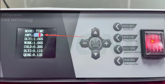
VI. Selection of Welding Mode (Time/Energy/Depth)
effect
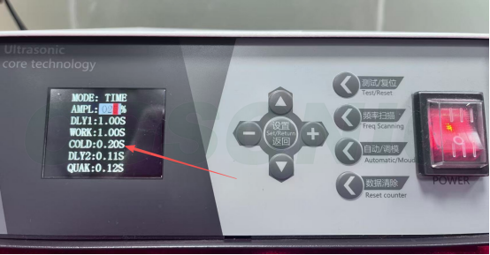
The precision ultrasonic welding machine offers three operating modes, distinguished by their "output criteria":
- Time mode : Outputs ultrasound at fixed intervals (controlled by "seconds").
- Energy Mode : Outputs total energy to offset voltage fluctuations (controlled by "Joules").
- Depth mode : Controlled by the depth of the welding head pressing down (in millimeters).
Applicable Scenarios
- Time mode : Stable product dimensions and good material consistency, the most commonly used mode, and the first choice for beginners to debug.
- Energy mode : Recommended for mass production where stable quality is required and for workshops with fluctuating power supply voltage.
- Deep mode : Scenarios with strict requirements on the overall height of the product and the amount of material overflow in the appearance (such as precision electronics and medical devices).
suggestion
Beginners should start with time mode for debugging , and then switch to energy or depth mode after becoming familiar with it; standard models only support time mode, please contact the equipment supplier for high-end models.
VII. Descent speed
effect
The downward movement speed of the horn. The descent speed directly affects the impact force at the moment the welding head makes contact with the product.
Influence
- The descent speed is too fast : the welding head hits the product, and the impact causes the product to shift, crack, or misalign.
- The rate of decline is too slow : This lengthens the entire production cycle and reduces capacity.
suggestion
- For precision-engineered or fragile parts, the descent speed should be slowed down; for ordinary structural parts, the speed can be increased appropriately.
It is recommended to start with a trial weld at 50% speed and adjust accordingly based on feedback on the product's appearance and strength.
8. Machine descent buffer
effect
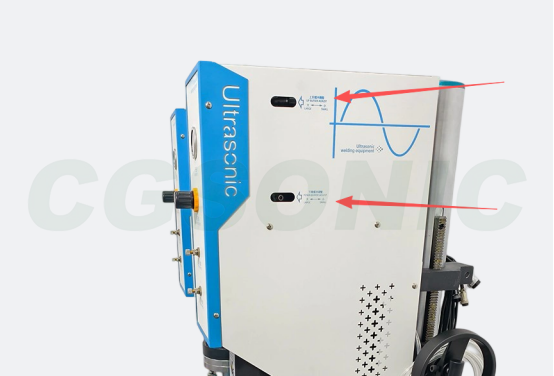
The buffer deceleration setting of the cylinder when the welding head descends and approaches the product is achieved through the buffer adjustment valves at both ends of the cylinder, which reduces the impact when the welding head contacts the product.
Influence
- Insufficient cushioning : The high-speed impact of the welding head on the product causes product displacement, cracks or positioning misalignment, and indentations are easily generated on the appearance parts.
- Excessive buffer : The descent rate is too slow, prolonging the production cycle and reducing capacity.
suggestion
- Buffer adjustment is usually achieved on the buffer adjustment valves at both ends of the cylinder ; clockwise adjustment increases buffering, and counterclockwise adjustment decreases it.
- Increase the buffer size for exterior parts, precision parts, and fragile parts; reduce the buffer size appropriately for ordinary structural parts to improve cycle time.
- Buffering and descent speed are two parameters that work together; adjusting either one alone has limited effect.
9. Triggering Pressure
effect
The ultrasonic waves are only output after the welding head reaches the set pressure in contact with the product. The trigger pressure is equivalent to a "fit confirmation switch".
Influence
- Trigger pressure too high : Ultrasonic stimulation is started before the pressure is fully compressed, causing vibration slippage and poor soldering.
- The trigger pressure is too low : it starts to vibrate before it is fully bonded, resulting in an unstable weld.
suggestion
- The trigger pressure should be slightly lower than the actual welding pressure to ensure that the product is fully bonded before starting the ultrasonic treatment.
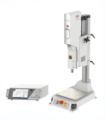
- Only high-end models (such as the HS series and P3 series) support the pressure trigger function; ordinary models do not have this option.
10. Delay Time Two (Preload Delay)
effect
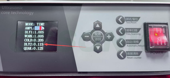
The delay time between the welding head descending and contacting the product and the start of ultrasonic wave output allows the product to fully adhere and stabilize under pressure before vibration begins; this is also known as pre-pressure delay.
Influence
- Too short a delay : The product starts vibrating before it is fully bonded, causing slippage, poor welding, and unstable welds.
- Excessive delay : The production cycle becomes longer, and continuous pressure may cause product deformation or damage.
suggestion
- For ordinary products , the time should be 0.05-0.2 seconds ; for large items or products that require pre-pressing and bonding, the time should be appropriately extended to 2-0.5 seconds .
- Use in conjunction with trigger pressure to ensure the product fits properly before activating ultrasonic output.
- Delay time 1 vs. Delay time 2 : One is the wait from "pressing the button to descending" (to protect the operator), and the other is the wait from "contacting the product to starting to vibrate" (to ensure a proper fit).
11. Second vibration time (cleaning the weld head)
effect
After the welding is completed and pressure is maintained, ultrasonic waves are output again for a short time to shake off the product or slag stuck to the welding head, preventing the welding head from sticking to the material and affecting the next cycle. Some models call this "demolding vibration" or "welding head cleaning time".
Influence
- Too short a time : Slag or product sticks to the welding head, affecting the positioning and weld quality of the next welding.
- Excessive time : Wastes energy, may cause the welding head temperature to rise too high, and accelerates welding head wear.
suggestion
- Materials that are easy to stick to (such as PP and PE) require a secondary shaking and dropping process; hard plastics are generally not easy to stick to.
- The normal setting is 05-0.2s ; extend the time appropriately for easily sticky materials; for non-stick products, set it to 0 to disable this function.
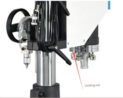
12. Fine-tuning of machine stroke
effect
Fine adjustment of the welding head's vertical stroke is used to precisely control the contact position and welding depth between the lowest point of the welding head and the product surface. This is usually achieved through limit screws or scale knobs.
Influence
- Excessive stroke : The welding head is pressed down too deeply, resulting in over-welding, flash, and product damage and deformation.
- Insufficient stroke : The welding head does not make proper contact or the pressure is insufficient, resulting in incomplete welding and insufficient welding strength.
suggestion
- First, make a coarse adjustment to the overall stroke, then use fine adjustments for precise positioning.
- Each adjustment should not exceed 1mm . While adjusting, test welds should be performed, and the results should be confirmed by combining appearance and strength inspections.
- After changing products or welding heads, the stroke fine-tuning must be recalibrated.
13. Machine Leveling Calibration
effect
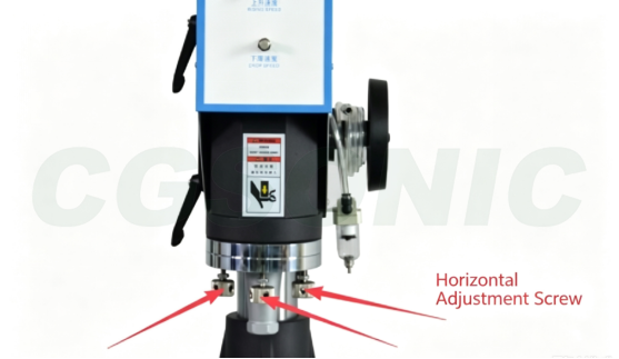
Aligning the parallelism between the working surface of the welding head and the working surface of the bottom mold/fixture ensures that the welding pressure is evenly distributed throughout the weld, which is the basis for guaranteeing consistent welding quality.
Influence
- Horizontal deviation : one side of the weld is over-welded while the other side is under-welded, resulting in uneven welding strength and easy product deformation.
suggestion
- Horizontal alignment is typically achieved by adjusting the level screws on the welding head mounting bracket.
- The level must be recalibrated after changing the welding head, changing the bottom mold, or moving the machine.
- Pressure distribution can be tested using pressure-sensitive paper or aluminum foil to confirm the horizontal state.
- Leveling must be performed after each change of welding head or mold; during production, the level should be checked regularly (weekly or monthly), and any deviations should be adjusted promptly.
XIV. Total Machine Stroke
effect
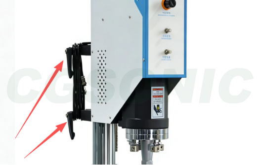
Controls the total range of motion of the entire machine body as it rises or falls, used to adjust the initial distance and maximum downward pressure between the horn (welding head) and the product, and to determine the range of product heights that can be adapted.
Influence
- Excessive total stroke : The welding head descends too far, increasing the cycle time and potentially exceeding the effective stroke range of the cylinder.
- Insufficient total stroke : The welding head cannot reach the product, or the welding depth is insufficient, resulting in a cold weld.
suggestion
- When switching to products of different heights, the total travel needs to be reset.
- The welding head is set according to the product height to ensure that the product can be easily picked up and put down when it is at its highest point, and that welding can be completed when it is at its lowest point.
- First, make a rough adjustment to the overall travel, and then make fine adjustments to the travel for precise positioning.
14-Parameter Quick Reference Table
|
Serial Number |
parameter |
Reasonable range |
The impact of adjustment |
The effect of reducing |
|
1 |
Welding pressure |
Medium (depending on model) |
Over-welding, pressure damage and deformation |
Poor soldering, insufficient strength |
|
2 |
Delay time 1 |
0.1-0.5s |
Production capacity decline |
Pressing down, product shifting |
|
3 |
Welding time |
0.1-1.2s |
Burnt, burrs, deformed |
Poor soldering, insufficient strength |
|
4 |
Holding time |
0.2-0.8s |
slow down |
Weld cracking and springback |
|
5 |
amplitude |
30%-80% |
Burning material, cracking thin walls |
Poor soldering, weak fusion |
|
6 |
Welding mode |
Time/Energy/Depth |
Choose according to the scenario |
|
|
7 |
descent speed |
30%-70% |
Product displacement, cracks |
slow down |
|
8 |
Falling Buffer |
Valve position 1-3 turns |
slow down |
Impact, indentation |
|
9 |
Triggering pressure |
Slightly lower than welding pressure |
Slippage, cold solder joint |
Premature oscillation and instability |
|
10 |
Delay time 2 |
0.05-0.5s |
Slower tempo, crush injuries |
Slippage, cold solder joint |
|
11 |
Secondary shaking |
0.05-0.2s |
Welding head temperature rise and wear |
Adhesion, positioning offset |
|
12 |
Slight adjustments to the itinerary |
0.1mm step |
Over-soldering, pressure damage |
Inadequate contact, poor soldering |
|
13 |
Horizontal calibration |
Pressure-sensitive paper test |
Must be uniform |
|
|
14 |
Total Itinerary |
Depending on product height |
Slower tempo, overtravel |
Unable to weld, poor weld |
Parameter Tuning Decision Tree
When encountering welding abnormalities, checking in the following order can cover 90% of the problems:
① Raw material drying (ABS/PC 80-100°C, 2-4 hours) → ② Product fit clearance and positioning → ③ Welding head/bottom mold condition (wear, resonance, level) → ④ Three main parameters: pressure, time, and amplitude → ⑤ Secondary parameters such as pressure holding, buffering, and stroke
First, rule out three main categories of problems: materials, positioning, and molds , before adjusting parameters. Reversing this order will waste time in the wrong direction.
General debugging steps
- First, confirm that the welding head and bottom mold fixture are installed in place and that the product positioning is not off.
- Set the pressure and amplitude to medium values initially, and gradually increase the welding time.
- First, check the appearance: for burns, burrs, or dents; then perform a breakage test to check the weld strength.
- Insufficient strength: Prioritize increasing the time or amplitude slightly, and avoid adjusting the parameters too much at once.
- If the welding material has burned out: reduce the time, amplitude, or pressure.
- Once the parameters are properly adjusted, save the formula for future use when switching products.
Common debugging mistakes
- They immediately set the time and amplitude to the maximum, directly damaging the product.
- Only checking the appearance of the weld without conducting a breakage test leads to a large number of poorly welded areas.
- Adjusting only the time while ignoring the coordination of pressure, amplitude, and pressure holding.
- The incoming materials were changed, but the old parameters were used, resulting in batch defects.
- Without saving the formula, you have to start from scratch every time you change products, which is inefficient and prone to errors.
Frequently Asked Questions (FAQ)
Q: Which parameter should I start with when adjusting ultrasonic welding parameters?
A: We recommend following the principle of "positioning first, then parameters." First, confirm that the welding head and bottom mold are installed in place and that the product is positioned correctly. Then, set the pressure and amplitude to medium levels, and gradually increase the welding time. First, check the appearance (no burning, burrs, or pressure marks), and then perform a breakage test to check the strength. Setting the time and amplitude to maximum at once is a common mistake for beginners and will directly damage the product.
Q: What is the appropriate welding time setting?
A: There's no absolute value; it depends on the product's wall thickness, material, and weld area. For small, thin parts, it's generally 0.1-0.4 seconds; for medium to large parts, 0.4-1.2 seconds. The principle of adjustment is to start with a short time and gradually increase it. If burning or excessive burrs occur, immediately adjust back. The most common mistake beginners make is setting the time to over 1.5 seconds at once, which will burn through the material.
Q: How do I adjust the amplitude percentage?
A: Hard plastics (PC, ABS) require a higher amplitude (60%-80%), while soft plastics (PP, PE, non-woven fabrics) should use a lower amplitude (30%-50%). It is recommended to start with the middle setting of the equipment (generally 50%), and then fine-tune it up or down if problems occur. Do not start at the maximum amplitude immediately. Excessive amplitude will crack thin-walled parts and accelerate the wear of the welding head.
Q: How do I choose between Time Mode, Energy Mode, and Depth Mode?
A: Time mode outputs ultrasound for a fixed duration, suitable for products with stable dimensions and good material consistency; it is the most common mode. Energy mode outputs total energy, which can offset power supply voltage fluctuations and is suitable for mass production with stable quality requirements. Depth mode controls the depth of the welding head, suitable for scenarios with strict requirements on the total height of the product and material overflow. Beginners should start with time mode for debugging, and for mass production stability, prioritize energy or depth mode.
Q: What are the differences between trigger pressure, delay time one, and delay time two?
A: These three parameters control the welding start-up sequence. The first delay time is the waiting time from pressing the button to the welding head descending (0.1-0.5s), allowing the operator to confirm the product is stable. The second delay time is the pre-pressure delay (0.05-0.5s) from the welding head pressing against the product to the start of ultrasonic output, allowing the product to fully adhere. The trigger pressure is the ultrasonic start-up only after the welding head contacts the set pressure (only available on high-end models), ensuring adhesion before vibration begins. Using these three parameters together can prevent abnormalities such as pressure on the hand, slippage, and incomplete welds.
Q: What is the purpose of the secondary vibration time (weld head cleaning time)?
A: After welding, ultrasonic waves are output again shortly to shake off any product residue or molten material adhering to the welding head, preventing material adhesion from affecting positioning in the next cycle. This setting is mandatory for easily adhesive PP and PE materials; for hard plastics (ABS, PC), which are generally not easily adhesive, a setting of 0 is acceptable. A setting of 0.05-0.2 seconds is typically used; excessively long settings will accelerate welding head wear and temperature rise.
Q: Should I save the recipe after adjusting the parameters?
- A: It is essential to save the settings. After adjusting the parameters for each product, it is recommended to save it in the equipment as a named formula (e.g., "ABS-shell-A1-formula"). This allows for direct use when changing products, avoiding the need for re-adjustment each time. When the batch of injection molding materials changes, the parameters need to be re-verified; the old formula cannot be directly applied.