



Ultrasonic Horn Design Guide: Sonotrode Design for Every Plastic Material
Ultrasonic Horn Design Guide: Sonotrode Design for Every Plastic Material
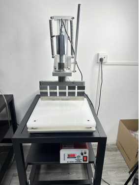
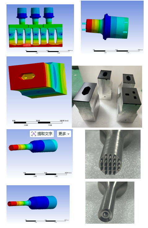
The ultrasonic horn — also called sonotrode, ultrasonic tool or ultrasonic mold — is the component that carries vibration energy from the converter straight into the plastic part. No single horn welds every resin well. In practice, poor ultrasonic horn design is the single most common root cause of low weld strength, surface whitening, burn marks, excess flash, part cracking and unstable output in mass production. This guide sets out how to design the horn base material, working frequency, amplitude and gain, and welding face structure resin by resin, so you can specify a custom ultrasonic horn that holds its tune on your line rather than one that merely fits your machine.
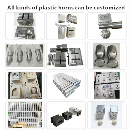
1. Why Horn Design Decides Whether the Weld Holds
A welding machine generates energy; the horn decides where, how fast and how evenly that energy reaches the joint. Three things happen inside the horn, and all three are fixed at design time, not at the control panel: acoustic transmission loss (how much amplitude arrives at the welding face), amplitude uniformity across the face (whether every point of the joint melts together), and mechanical resonance (whether the horn stays tuned at its design frequency under load). When ultrasonic horn design is wrong, operators compensate by raising pressure or weld time — which is exactly how whitening, burn and flash appear.
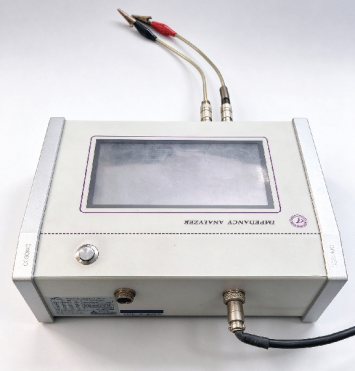
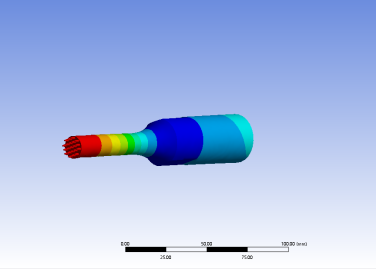
The practical consequence is that an ultrasonic welding horn is not a spare-part decision. It is a process decision. Changing resin, adding glass fibre, moving from a flat joint to a curved one, or raising the required pull strength all invalidate the previous horn design.

2. The Three Decisions Behind Every Ultrasonic Horn
Every ultrasonic horn design comes down to three decisions that are made in this order: base material first, frequency and amplitude second, welding face structure third. Reversing the order is how buyers end up with a horn that is geometrically correct but acoustically wrong for the resin.
|
Decision |
What it is governed by |
Typical mistake |
How to get it right |
|
1. Base material |
Acoustic loss, fatigue strength, wear resistance against filler |
Choosing 7075 aluminium for glass-filled resin and watching the face wear flat |
Match material to filler content and run length, not to price |
|
2. Frequency & amplitude |
Resin crystallinity, part size, wall thickness, heat sensitivity |
Running PP on a 40 kHz horn and wondering why the joint never melts |
Semi-crystalline resins need lower frequency and higher amplitude |
|
3. Welding face structure |
Joint geometry, cosmetic standard, airtightness and pull strength |
Copying a flat contoured face from an ABS part onto a nylon part |
Design energy director or shear joint for the resin, then contour the face |
3. Horn Base Material: 7075 Aluminium, Titanium or Hardened Tool Steel
Base material is the first ultrasonic horn design decision because it sets both the acoustic ceiling and the service life. Three materials cover essentially every production case: 7075 aluminium alloy, titanium alloy Ti-6Al-4V, and hardened tool steel with a nitrided surface. Each occupies a clear band, and the bands are defined by filler content and run length rather than by budget alone.
|
Material |
Acoustic & fatigue behaviour |
Best for |
Avoid when |
|
7075 aluminium alloy |
Very low acoustic loss, easy to machine, lowest cost; limited fatigue life and low wear resistance |
Prototyping, pilot runs, small batches, unfilled resins such as ABS and PS |
Long continuous runs, glass-filled or mineral-filled resin, high-amplitude duty |
|
Titanium alloy Ti-6Al-4V |
Balanced acoustic transmission and fatigue strength; holds tune over long runs |
Mass production of PP, PC, nylon, transparent parts and continuous duty |
Heavily filled abrasive resin where face wear dominates life |
|
Hardened tool steel, nitrided |
Excellent wear resistance; higher density and slightly higher internal loss, so more generator load |
Glass-filled, carbon-filled and mineral-reinforced plastics; rolling cutting and webbing cutting horns |
Thin-wall heat-sensitive parts where every micron of amplitude matters |
Buyer tip: ask the supplier which material they are quoting, not just which frequency — material is the first of the three ultrasonic horn design decisions and the easiest one to leave off a quotation. A 20 kHz titanium horn and a 20 kHz aluminium horn look identical on a quotation line and behave completely differently after three months of two-shift production.
One special case deserves its own note: rolling cutting and webbing cutting. Continuous nylon webbing cutting runs the horn at high amplitude for hours against an abrasive fibre surface, which is exactly the combination that destroys aluminium faces. For webbing welding and cutting duty, specify a hardened steel cutting horn (or a titanium body with a replaceable steel insert) and plan face re-machining into the maintenance cycle.
4. Frequency: 15 kHz to 40 kHz and What Each Band Is For
Frequency is the second ultrasonic horn design decision, and it sets the amplitude ceiling and the size of part you can drive. Lower frequency means larger wavelength, larger horns, higher achievable amplitude and better reach into big parts; higher frequency means finer control, smaller horns and less heat input into thin walls. Pick the band from part size and wall thickness, then let the resin push you one step lower or higher inside that band.
|
Frequency |
Typical peak amplitude |
Best for |
Note for the buyer |
|
15 kHz |
50–70 μm |
Very large parts, long weld lines, high-amplitude duty |
Large heavy horn; needs a machine with matching power headroom |
|
20 kHz |
30–50 μm |
Large parts and large weld areas, semi-crystalline resins |
The default band for PP, PE and glass-filled parts |
|
28–30 kHz |
20–30 μm |
General-purpose small and medium plastic parts |
The most common band in job-shop and consumer-electronics welding |
|
35–40 kHz |
10–20 μm |
Precision thin-wall parts, heat-sensitive and cosmetic parts |
Lower heat input, less whitening; shorter horn life at high amplitude |
5. Amplitude and Gain: Matching How the Resin Melts
Amplitude is how far the welding face moves; gain is how much the horn multiplies the converter's output to reach that amplitude. Both are ultrasonic horn design parameters, and both are chosen from the resin's melt behaviour rather than from the machine's maximum rating. A higher-gain horn delivers more amplitude from the same generator, which is what semi-crystalline resins need — but it also raises internal stress in the horn, which is why gain is limited by material and by horn geometry.
This rule of thumb holds across most production floors and is the fastest way to sanity-check an ultrasonic horn design: amorphous resins melt smoothly at moderate amplitude, while semi-crystalline resins need a sharp, high-energy impulse because they absorb ultrasonic energy rapidly and re-solidify fast. That difference is the whole reason one horn cannot serve both ABS and PP.
6. Amorphous vs Semi-crystalline: the Root Rule
f you remember one table from this guide, remember this one. Resin crystallinity predicts frequency, amplitude, joint structure and horn material better than any other single property.
|
Property |
Amorphous |
Semi-crystalline |
What it means for the horn |
|
Typical resins |
ABS, PC, PMMA, PS, SAN, PVC |
PP, PE, POM, PA6/PA66, PBT, PET |
Identify the family before anything else |
|
Melting behaviour |
Softens over a wide temperature range |
Sharp melting point, re-solidifies quickly |
Semi-crystalline needs fast, concentrated energy delivery |
|
Energy absorption |
Transmits ultrasonic energy efficiently |
Absorbs energy quickly, hard to drive to the joint |
Semi-crystalline needs more amplitude at the face |
|
Frequency & amplitude |
Higher frequency, medium-low amplitude |
Lower frequency, higher amplitude |
This is the single most useful design rule |
|
Preferred joint |
Standard 90° triangular energy director works well |
Enlarged energy director or shear joint |
Joint design follows the resin, not the drawing convention |
|
Process window |
Wide and forgiving |
Narrow; small drift causes rejects |
Semi-crystalline parts need stored parameters and tighter control |
7. Plastic-by-Plastic Horn Design Map
This is the reference table buyers ask for when they start a horn design project. It maps each common resin to the horn material, frequency band, joint structure and the failure mode to watch for on the line. Use it to write your specification, then confirm it with a weld sample on your own tooling.
|
Resin |
Horn material |
Frequency |
Joint & face design |
Failure to watch |
|
ABS / HIPS (amorphous) |
7075 aluminium for prototype, titanium for volume |
20–40 kHz all workable |
Standard 90° triangular energy director; flat or contoured face |
Over-energy yellowing and bubbles; control weld time |
|
PC polycarbonate (amorphous) |
Titanium, smooth polished face |
35–40 kHz preferred |
Smooth contact surface, uniform pressure, supportive fixture |
Whitening and cracking; cosmetic parts need low amplitude |
|
PMMA acrylic (amorphous) |
Titanium, polished face |
35–40 kHz |
Fine energy director, gentle amplitude ramp |
Crazing and stress whitening near the weld line |
|
PS / SAN (amorphous) |
7075 aluminium or titanium |
28–40 kHz |
Standard energy director; light contact pressure |
Burn marks from excess amplitude |
|
PP polypropylene (semi-crystalline) |
Titanium, higher gain |
20 kHz widely used |
Enlarged energy director; shear joint recommended for strength |
Incomplete melt and weak pull strength if amplitude is low |
|
PE polyethylene (semi-crystalline) |
Titanium, higher gain |
20 kHz |
Large energy director or shear joint; generous weld stroke |
Unstable joint; near-field welding distance must be checked |
|
POM polyacetal (semi-crystalline) |
Titanium |
20–30 kHz |
Shear joint outperforms basic energy director |
Fast re-solidification; short delay time before pressure hold |
|
PA6 / PA66 nylon (semi-crystalline) |
Titanium for volume; hardened steel if glass-filled |
20–30 kHz |
Shear joint; rapid energy delivery |
Moisture content in the resin changes weld consistency |
|
PET / PBT (semi-crystalline) |
Titanium preferred; hardened steel for glass-filled grades |
20–30 kHz |
Concentrated energy director; avoid broad flat vibrating faces |
Delamination and whitening from wide-face vibration; heavy abrasion when glass-filled |
|
PC/ABS blend |
Titanium |
28–35 kHz |
Standard energy director; tune between the two base resins |
Blend ratio changes the process window between lots |
|
Glass-filled resin (GF20–GF40) |
Hardened tool steel, nitrided surface, reinforced face |
20 kHz typical |
Enlarged energy director; wear allowance built into the face |
Face wear, detuning, and filler-rich weak weld line |
|
Carbon-filled / mineral-filled |
Hardened tool steel, nitrided |
20 kHz typical |
Reinforced face structure; pressure spread evenly |
Rapid abrasion and electrical conductivity near the fixture |
Two practical cautions. First, "glass-filled" is not one material: GF20 and GF40 behave differently, and the filler type (short glass fibre, long glass fibre, mineral) changes both wear and weldability. Second, regrind and lot-to-lot resin variation move the process window; a horn that was tuned on virgin resin may need re-tuning on a regrind blend.
8. Energy Director vs Shear Joint
The joint structure is where resin behaviour meets part geometry. A triangular energy director concentrates energy into a small contact area and melts quickly; a shear joint melts a vertical interference fit while the parts slide past each other, producing a stronger and better sealed bond. Choosing between them is part of ultrasonic horn design because the horn face has to match the joint it is driving.
|
Joint type |
How it works |
Best for |
Limitation |
|
90° triangular energy director |
A small triangular ridge concentrates energy and melts first |
Amorphous resins, general-purpose parts, wide process window |
Limited strength and seal compared with shear |
|
60° or enlarged energy director |
More melt volume at the joint |
Semi-crystalline resins that need a bigger melt start |
More flash to manage on cosmetic parts |
|
Shear joint |
Vertical interference melts while parts slide, giving a large weld area |
Semi-crystalline resins, airtightness and high pull strength |
Needs tighter part tolerances and accurate fixturing |
|
Step joint / tongue and groove |
Locating feature plus weld surface |
Parts needing alignment before welding |
More complex tooling and higher part cost |
9. Welding Face Profile and Surface Finish
The welding face must follow the part surface. If the horn contour does not match the part, contact pressure concentrates on the high points, the low points never melt and the result is a partially welded part that passes visual inspection and fails pull testing. This is the most common geometry fault in ultrasonic horn design and the easiest to prevent at drawing stage.
- Contour the face to the part: on curved or stepped parts, machine the horn face from the same 3D model as the part, not from a flat approximation.
- Keep the surface smooth on cosmetic and transparent parts: a rough or knurled face leaves imprint marks and stress-whitening on PC and PMMA.
- Use knurling only where slip is a real problem, and accept the imprint: knurl raises friction but always marks the part surface.
- Balance the face: an asymmetric horn face sends amplitude to one side; symmetrical shapes hold tune better and wear evenly.
- Agree the surface finish in writing: polished contact zone for cosmetic parts, nitrided face for filled resin, and a stated Ra value in the RFQ.
10. Filled and Reinforced Plastics: Wear, Nitriding and Horn Life
Filler content is where ultrasonic horn design stops being theoretical. Glass fibre, carbon fibre and mineral fillers abrade the welding face continuously. On unfilled resin the face finish barely changes over a million cycles; on GF30 the same horn can lose enough profile to detune within weeks. For these resins the standard answer is a hardened tool steel horn with nitrided surface and a reinforced face structure, with wear allowance designed in so the horn stays in tune as it wears.
Note the trade-off: hardened tool steel is denser and has slightly higher internal loss than titanium, so it asks more from the generator for the same amplitude. That is acceptable when the alternative is replacing an aluminium horn every few weeks, but it should be a deliberate decision rather than a default.
11. Technical Parameters
|
Parameter |
Options |
How to choose |
|
Horn base material |
7075 aluminium alloy / titanium alloy Ti-6Al-4V / hardened tool steel with nitrided surface |
Aluminium for prototype and small batches; titanium for volume and continuous duty; hardened nitrided steel for glass-filled, carbon-filled and mineral-filled resin |
|
Working frequency |
15 / 20 / 28 / 30 / 35 / 40 kHz |
15–20 kHz for large parts, large weld areas and semi-crystalline resin; 28–30 kHz for general small and medium parts; 35–40 kHz for precision thin-wall, heat-sensitive and cosmetic parts |
|
Peak amplitude at the face |
10–20 μm (35–40 kHz) / 20–30 μm (28–30 kHz) / 30–50 μm (20 kHz) / 50–70 μm (15 kHz) |
Amorphous resin at the low end of the band, semi-crystalline at the high end |
|
Amplitude gain |
Set by horn geometry and material; higher gain raises internal stress |
Higher gain for semi-crystalline resin, but stay inside the limit your horn material allows |
|
Welding face |
Flat / contoured / knurled / polished / nitrided |
Contoured from the part 3D model; polished for cosmetic and transparent parts; nitrided for filled resin |
|
Joint structure |
90° triangular energy director / enlarged energy director / shear joint / step joint |
Energy director for amorphous; enlarged director or shear joint for semi-crystalline; shear joint for airtightness and pull strength |
|
Machine power |
Handheld gun 100–800 W; benchtop 800–2000 W |
Size generator headroom for the horn material and weld area, not just for the part size |
|
Applications |
Spot welding, continuous sealing, cutting, riveting, insert embedding |
Declare the process at RFQ stage; each one needs a different face and amplitude |
12. A 6-Step Ultrasonic Horn Design Process
- Identify the resin precisely: grade, filler type and filler percentage, plus whether regrind is used. Filler content drives horn material more than anything else.
2. Classify the resin as amorphous or semi-crystalline. This sets the frequency band and whether you need low or high amplitude.
3.Define the joint and the requirement: weld strength, airtightness, cosmetic standard, and whether a shear joint is feasible on your part geometry.
4. Choose the horn base material from filler content and run length: aluminium for prototype, titanium for volume, nitrided hardened steel for abrasive filler.
5.Fix the frequency and amplitude from part size and wall thickness, then confirm the horn geometry can deliver that amplitude at your required face area.
6. Send drawings and parts for a weld sample, and judge the supplier on the sample report: cross-section photo, measured pull strength or leak rate, and stated amplitude and frequency.
13. Five Ultrasonic Horn Design Mistakes
Every one of these five appears on real production floors, and every one is a symptom of a decision made too late. Treat them as a review list: if your ultrasonic horn design skipped any of these questions, the problem surfaces after the tooling is paid for.
|
Mistake |
Why it happens |
Consequence |
Fix |
|
Using one universal horn for ABS and PP |
Both are common commodity resins and the parts look similar |
PP never reaches full melt, or ABS is over-welded and yellows |
Select frequency and amplitude per resin family |
|
Rough, high-amplitude face on transparent PC |
Copying a face design that worked on opaque ABS |
Whitening, imprint marks, cosmetic rejects |
Polished contact face, lower amplitude, supportive fixture |
|
Aluminium horn on glass-filled resin |
Aluminium is the cheapest and fastest horn to make |
Face wears flat, horn detunes, weld strength drifts |
Nitrided hardened tool steel with wear allowance |
|
Flat face on a curved part |
Horn quoted from a 2D drawing instead of the 3D model |
Uneven pressure, partial weld, parts that pass visual but fail pull |
Machine the face from the part 3D model |
|
Buying on frequency and price only |
Material and gain are not listed on the quotation |
Two horns with identical specs behave differently in production |
Specify material, gain, face finish and tuning report in the RFQ |
14. Horn Life, Detuning and Re-tuning
A horn does not usually fail suddenly; it drifts. Face wear, small cracks at the nodal roots, loose stack bolts and contamination on the mating surfaces all shift the resonance frequency away from the generator's band. On the line this shows up as rising weld time to get the same result, more rejects at the edge of the process window, audible harshness from the stack, or heat at the horn-to-booster joint. Every one of those is a maintenance signal, and it is why an ultrasonic horn design should always include a re-tuning plan.
Plan for it: ask your supplier how the horn will be re-tuned after wear, whether re-machining the face is possible within the design allowance, and what the turnaround is. A custom ultrasonic horn is a maintained component, not a consumable you throw away — and the supplier who tells you the maintenance path is usually the one whose horns are designed with that path in mind.
15. RFQ Package: What to Send Your Horn Supplier
A horn quotation is only as good as the information behind it. Send this package and you will get comparable quotes instead of three different guesses.
- Resin specification: grade, filler type and percentage, regrind ratio, and moisture sensitivity for nylon.
- Part drawing or 3D model, with the joint location marked and the wall thickness at the weld.
- : Weld requirement: pull strength target, airtightness or leak rate, cosmetic standard and whether the weld line is visible.
- Machine details: existing generator frequency, available power, and whether the press is pneumatic or servo.
- Production context: pieces per shift, shift pattern, and target cycle time.
- Ask them to quote back: horn material, frequency, gain, face finish, tuning report and sample weld report.
16. Cost and Lead Time
Horn cost is driven less by material weight than by design work, tuning and verification — the parts of an ultrasonic horn design that never appear on the quotation line. Understanding where the money goes helps you judge whether a cheap quotation is actually a cheap horn.
|
Cost or time item |
What drives it |
Note for the buyer |
|
Base material |
Aluminium lowest, titanium mid, hardened nitrided steel highest |
Material is a smaller share of cost than buyers expect |
|
Design and simulation |
Complexity of the face contour and the number of design iterations |
A supplier who simulates before cutting usually saves you a re-make |
|
Machining and tuning |
Tolerance, surface finish requirement, nitriding |
Ask whether tuning is done on the actual generator |
|
Sample weld verification |
Whether you send parts, and how many iterations |
Insist on a report with measured values, not a photo only |
|
Lead time |
Material availability, nitriding queue, tuning and sample loop |
Budget the sample loop; it is usually the longest part |
|
Re-tuning and repair |
Wear rate of your resin and your maintenance routine |
Ask for the re-tuning path and turnaround before you buy |
17. Eight-Question Self-Check Before You Enquire
|
# |
Question |
If the answer is no |
|
1 |
Do you know the exact resin grade, filler type and filler percentage? |
Get the datasheet first; the horn material depends on it |
|
2 |
Have you classified the resin as amorphous or semi-crystalline? |
This decides frequency and amplitude before anything else |
|
3 |
Is the joint structure decided, or still open to the supplier? |
Decide it jointly; the horn face has to match it |
|
4 |
Do you have a 3D model of the part surface at the weld? |
Request it from your tooling team; a 2D drawing causes mismatch |
|
5 |
Is the requirement written as a number: pull strength, leak rate, appearance grade? |
Unwritten requirements become arguments after delivery |
|
6 |
Do you know your machine frequency and available power? |
Check the generator nameplate before ordering a horn |
|
7 |
Can you send real parts for a weld sample? |
A horn quoted without samples is a guess |
|
8 |
Have you asked what happens when the horn wears? |
Ask for the re-tuning and re-machining path |
18. Final Summary
Ultrasonic horn design is a chain of three decisions: base material from filler content and run length, frequency and amplitude from resin crystallinity and part size, and welding face structure from joint geometry and requirement. Break the chain at any point and the symptom appears later as weak welds, whitening, flash or drift in mass production. Specify all three in writing, verify with a weld sample on your own parts, and treat the horn as a maintained component with a defined re-tuning path.
If you send resin specification, part 3D model, weld requirement and machine frequency, a serious supplier returns a horn material recommendation, a frequency and amplitude proposal, a joint design suggestion and a sample weld report — that package, not the price line, is what tells you whether the ultrasonic horn design will hold on your line.
19. Our Service
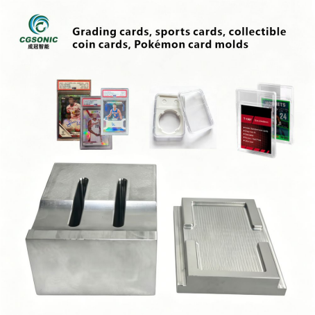
Shenzhen Chengguan Intelligent Ultrasonic Equipment Co., Ltd. customizes ultrasonic horns, boosters and anvil fixtures to your part drawings, resin grade and capacity target. Every horn is delivered with frequency tuning, sample welding on your own parts and after-sales calibration support, for both handheld and benchtop ultrasonic welding machines.
Applications cover webbing welding and cutting, plastic sealing, automotive components, electronic housings and more. Send your resin specification and part model, and we will return a horn material recommendation with a sample weld report before you commit to production.
20. FAQ
Q: What is the difference between an ultrasonic horn, a sonotrode and an ultrasonic mold?
A: They are three names for the same component in most plastic welding contexts: the tuned metal body that transfers vibration from the converter and booster into the part. "Sonotrode" is the standard European term, "horn" is the common industrial term, and "ultrasonic mold" or " ultrasonic tool" is widely used in Asian supply chains. What matters is not the name but the specification behind it: base material, frequency, gain, face contour and tuning — the five items that make up an ultrasonic sonotrode design.
Q: Which horn material should I choose: 7075 aluminium, titanium or hardened tool steel?
A: Choose by filler content and run length rather than by price — this single decision drives most of the ultrasonic horn design outcome. 7075 aluminium has the lowest acoustic loss and cost and is right for prototyping, pilot runs and unfilled resins such as ABS and PS, but it wears quickly and has limited fatigue life. Titanium alloy Ti-6Al-4V balances acoustic transmission and fatigue strength and is the mainstream choice for volume production, continuous duty and resins such as PP, PC and nylon. Hardened tool steel with a nitrided surface is the answer for glass-filled, carbon-filled and mineral-reinforced plastics, where abrasion — not fatigue — sets the service life.
Q: Why should an aluminium horn not be used long-term on glass-filled plastic?
A: Glass fibre acts like sandpaper against the welding face. Under high-frequency vibration the fibres abrade the softer aluminium surface rapidly: the face geometry changes, the horn drifts off resonance, weld consistency collapses and the horn fails far earlier than its rated life. For glass-filled resins, specify titanium or a nitrided hardened steel horn and budget for face re-machining.
Q: Why can one horn not weld both ABS and PP well?
A: Because they sit on opposite sides of the crystallinity divide. ABS is amorphous: it softens over a wide temperature range, transmits ultrasonic energy efficiently and melts at moderate amplitude and higher frequency. PP is semi-crystalline: it has a sharp melting point, absorbs ultrasonic energy rapidly and re-solidifies fast, so it needs lower frequency with higher amplitude and usually an enlarged energy director or a shear joint. A horn tuned for one delivers either too little energy or too much for the other, which is why the same horn produces weak PP welds or over-welded ABS.
Q: How do I choose between a 90° energy director and a shear joint?
A: Start from the resin, then from the requirement. A 90° triangular energy director is the standard solution for amorphous resins and general-purpose parts: it concentrates energy, melts quickly and gives a wide process window. A shear joint melts a vertical interference fit while the parts slide, producing a much larger weld area, and is preferred for semi-crystalline resins and wherever airtightness or high pull strength is specified. The cost is tighter part tolerances and more accurate fixturing, so confirm your mould capability before committing to shear.
Q: Do I really need a custom ultrasonic horn, or will a standard one do?
A: For production, you need a custom horn. The welding face has to follow your part surface, the amplitude has to suit your resin, and the resonance has to match your generator frequency — three variables that are specific to your part, your material and your machine. Standard catalogue horns work for simple flat parts and trials. On any part with a contour, a cosmetic surface, a filled resin or a documented strength requirement, a custom ultrasonic horn is the normal specification rather than a paid upgrade.
Q: How long does an ultrasonic horn last, and how do I know when it needs re-tuning?
A: Life is set by material, amplitude, resin filler and maintenance, not by a fixed cycle count, so treat it as an ultrasonic horn design criterion rather than a warranty number. Aluminium horns on filled resin can wear out of tune within weeks; titanium horns on unfilled resin often run for years. Warning signs are a rising weld time to reach the same result, more rejects at the edge of the process window, a harsher sound from the stack, heat at the horn-to-booster joint, or visible wear and polishing of the welding face. Any of these means measure the resonance and re-tune before the horn cracks.
Q: Can one horn handle several different products?
A: Only within limits. One horn can serve several parts if they share resin family, similar weld area and similar joint geometry, and if the amplitude requirement falls in the same band. Switching between amorphous and semi-crystalline resins, or between flat and contoured faces, generally needs a different horn. If you run a product family, ask your supplier to design a common horn around the most demanding part rather than buying the cheapest horn that fits the easiest one.
Q: What should I send to get an accurate ultrasonic horn quotation?
A: Resin specification with filler type and percentage, part drawing or 3D model with the joint marked, weld requirement written as numbers (pull strength, leak rate, cosmetic grade), your machine frequency and available power, and pieces per shift with target cycle time. Ask the supplier to quote back horn material, frequency, gain, face finish, a tuning report and a sample weld report with measured values. A quotation that only states frequency and price is not comparable with one that states all of these.